


3. Geometric correction of an aerial image of South Caicos Island
Author: Dr Alasdair.J.Edwards, University of Newcastle, UK.
Aim of Lesson
To learn how to rectify an image to a Universal Transverse Mercator (UTM) coordinate system and to understand why it is important to carry out geometric correction of remotely sensed images.
Learning Objectives
To understand that measurements made from images that have not been geometrically corrected can be misleading and that just because an image looks like a map it does not necessarily have the properties of a map.
To learn how to make measurements of distances between points on an image using Pythagoras' theorem so that you can compare distances between known points before and after rectification and georeferencing of the image.
To discover how Ground Control Points (GCPs) are obtained at selected positions, which are carefully chosen to be readily identifiable on the image, using a Global Positioning System (GPS) so that the geographical coordinates of a series of pixels can be linked together in a rectification table.
To understand how a rectification table works by linking pixels at known column and row coordinates to GCPs at know geographical (in this case-study, Universal Transverse Mercator) coordinates obtained using a GPS.
To use Bilko to enter details of three GCPs in the rectification table and learn how to select an appropriate transformation (linear, quadratic or cubic) for rectification.
To understand what Root Mean Square (RMS) error means and find out how to deselect problem GCPs that have unacceptably high RMS errors (perhaps due to a GPS error or human error in transcribing coordinates).
To carry out rectification and resampling of the image to the Universal Transverse Mercator (UTM) grid system of local maps of the Turks & Caicos Islands.
To compare measurements between points on the geometrically corrected and uncorrected images and see how much positional error may result from using uncorrected imagery.
How to download the lesson
Lesson overview
Part of a scanned (approximate pixel size 3.5 m x 3.5 m) black and white aerial photograph of South Caicos Island, taken in 1981, is used for this lesson. You want to use this image to look at how parts of the island have changed and thus need to geometrically correct it and georeference it to the local map, which uses Universal Transverse Mercator (UTM grid zone 19 N) coordinates.
To rectify an image you need to relate specific pixels in the image to known map coordinates. The map coordinates of objects, which are clearly recognisable both on the ground and on the image, may be obtained from large-scale maps, directly using a GPS or from other images that are already georeferenced.
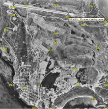
The raw aerial image with Ground Control Points (GCPs) superimposed. The mouse was hovering over GCP 001 and its details are displayed. Each GCP is chosen as being readily identifiable on both the ground and image, thus corners of salinas, large buildings, jetties and road junctions feature prominently.
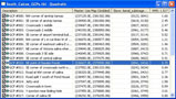
A Bilko rectification table which links the column and row coordinates of each GCP on the image to its UTM coordinates as measured using a Global Positioning System (GPS).
When you have enough GCPs you can get the computer to calculate a transformation (linear, quadratic or cubic), which maps the raw image grid to the new UTM grid. To assess the goodness of fit of both the overall transform and individual GCPs, the inverse of the transformation matrix is used to retransform the reference coordinates of the GCPs back to the source coordinate system. The distance between the input (source) location of a GCP and the retransformed coordinates of the same GCP is called the Root Mean Square (RMS) error. This is calculated for you in the rectification table (last column) as follows:
RMS error =
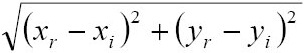
where xi and yi are the input (source) coordinates, and xr and yr are the retransformed coordinates.
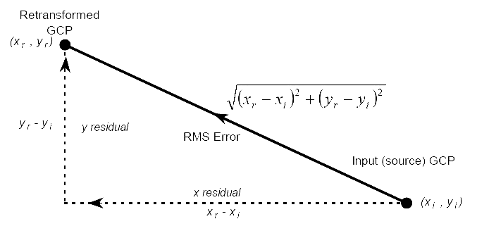
A diagram showing how one calculates the Root Mean Square error of an individual Ground Control Point. The RMS error is expressed in terms of numbers of pixels. Thus with a pixel size of 3.5 m, an average RMS error of 2, would represent 7 m.
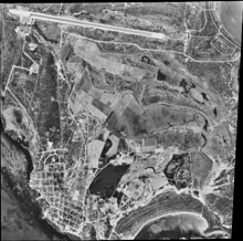
The resampled, georeferenced, aerial image showing the distortion of the original raw image.
References
Butler, M.J.A., LeBlanc, C., Belbin, J.A. and MacNeill, J.L. (1987). Marine resource mapping: an introductory manual. FAO Fisheries Technical Paper 274. 256 pp.
ERDAS Inc. (1994). ERDAS Field Guide. Third Edition. ERDAS Inc.: Atlanta.
Green, E.P., Mumby, P.J., Edwards, A.J. and Clark, C.D. (Ed. A.J. Edwards) (2000). Remote Sensing Handbook for Tropical Coastal Management. Coastal Management Sourcebooks 3. UNESCO, Paris. ISBN 92-3-103736-6 (paperback).
Mather, P.J. (1999). Computer Processing of Remotely-Sensed Images: An Introduction. Second Edition. John Wiley & Sons: Chichester. ISBN 0-471-98550-3 (paperback).
Wilkie, D.S. and Finn, J.T. (1996). Remote Sensing Imagery for Natural Resources Monitoring: A Guide for First-time Users. Columbia University Press: New York. ISBN 0-231-07929-X.
 Previous: Lesson 2
|
Last update: 20 August 2018 | Contact |  |
Site Policy |
Next: Lesson 4

|